The global CAD market will reach $13.83 billion by 2028, and computer aided design examples are evolving faster than ever. Many engineers use only a small portion of their CAD software’s capabilities, missing features that could improve their design outcomes.
Artificial intelligence, virtual reality, and automation are reshaping the scene of computer aided design technology and how we create and manufacture products. Advanced tools now provide capabilities like model-based definition – annotated 3D models with complete manufacturing information that don’t need separate drawings. Modern CAD software examples reduce repetitive tasks through automation, which saves valuable time during the design process.
Hidden features create more than just speed – they provide competitive advantage. PTC research reveals that manufacturers who use advanced CAD capabilities will lead in quality, cost, and time-to-market by 2025 and beyond. Cloud-based computer aided design software examples have become crucial for global team collaboration as industries accept remote work. This piece explores powerful yet overlooked features in popular CAD platforms that help you be proactive with industry changes.
Hidden Features That Streamline Early Design Stages
Most engineers miss out on key features that could speed up their early-stage design work. These hidden tools can cut design time and improve quality in computer aided design examples.
Sketch Constraints Auto-Detection in Solid Edge
Solid Edge has powerful sketch constraint tools that many professionals don’t use enough. Other CAD software shows constraint status right away, but Solid Edge needs more expertise to use well. Engineers often find it hard to tell if a sketch is fully constrained because the software doesn’t show the “Fully Defined” text like its competitors.
A simple technique can help you manage sketch stability better. You can place profiles in a circle and connect loose ends to it. This keeps everything consistent even during big parameter changes. The method stops dimensions and control lines from going off-screen during edits. Profiles stay in proper form on their own inside circular geometry, while loose elements tend to flip around or bulge as you modify them.
Design Intent Recognition in Siemens NX
Siemens NX comes with AI-powered predictive design intent that keeps important geometric relationships intact. Engineers can make quick changes while the software maintains key constraints like symmetry, alignment, and thickness. The Design Intent option in the command bar controls how edits spread through the model when you select a face.
The system recognizes various relationships including:
- Symmetric relationships about planes that automatically mirror edits across designs
- Concentric relationships ensuring holes remain perfectly centered
- Aligned holes maintaining cylindrical features on a shared axis
- Coplanar relationships updating multiple planar surfaces simultaneously
- Offset relationships preserving wall thickness when resizing features
This smart system cuts down on repeated work and keeps everything behaving consistently during changes. Engineers can focus on design instead of managing constraints.
Component Reuse Libraries in CATIA
CATIA makes assembly creation easier with its pattern reuse tools. Engineers can take patterns from Part Design (Rectangular, Circular, and User Pattern) and quickly set up multiple constraints in Assembly Design. This helps a lot with parts that need repeated placement, like fasteners.
CATIA’s Classification Manager role lets you build multi-level libraries to organize and find previous designs. The “IP Classify&Reuse” app has advanced search features that help you find parts based on their attributes and constraints. You can drag these parts straight into the CAD interface. This saves time by letting you reuse tested components throughout your projects.
Simulation-Driven Design Tools Engineers Rarely Use
Many professionals haven’t explored the simulation tools built into modern CAD platforms. These powerful features let engineers test designs virtually before physical prototyping. Studies show that only 30% of engineers use these capabilities in their daily work.
Real-Time Feedback Loops in Fusion 360
Fusion 360 merges manufacturing data directly into the design process. This creates quick feedback loops between design changes and manufacturing results. Engineers can spot and fix production issues right away instead of finding problems later. The software gathers data from CNC machines, 3D printers, and other equipment to help prevent downtime and lost productivity. The system sends quick alerts when a machine’s performance drops.
The cloud-based structure of Fusion 360 makes this important data available from anywhere. Teams can monitor and work together remotely. The Python-based feedback tool in the Fusion 360 API gives quick assessment of model quality by checking key metrics without supervisor input. Most engineers don’t know about this feature.
Integrated FEA in SolidWorks Simulation
SolidWorks Simulation offers a detailed suite of structural analysis tools using Finite Element Analysis (FEA). Most users don’t take full advantage of this powerful toolset that goes beyond simple static analysis:
- Motion and kinematic analysis for mechanical movement simulation
- Fatigue analysis for testing design life under varying loads
- Frequency (modal) analysis for determining natural frequencies
- Thermal analysis for understanding heat transfer through components
- Topology optimization for generating ideal shapes based on specified requirements
The National Agency for Finite Element Methods and Standards (NAFEMS) has confirmed the reliability of all study types in SolidWorks Simulation. FEA started in the 1940s but became available to more people through desktop computers in the 1980s and 90s. Now many computer aided design software examples include these features as standard.
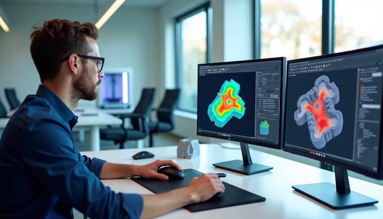
Thermal Mapping in Electronics CAD
Thermal simulation helps engineers learn about product behavior under different temperature conditions. This feature is particularly significant in electronics design to find hotspots, thermal gradients, and cooling problems before manufacturing starts. These tools use computational fluid dynamics (CFD) and finite element analysis to predict heat distribution in circuit boards and components.
Engineers can review different cooling methods like fans, heatsinks, and thermal vias to optimize designs for quality, efficiency, and cost. Teams can adjust their designs quickly based on simulation results to achieve the best performance in ground conditions.
Manufacturing-Ready Features Often Missed
Modern CAD systems pack powerful manufacturing features that many design engineers haven’t discovered yet. These tools connect theoretical designs to real-world production needs.
Lattice Structure Generation for 3D Printing
CAD systems now create complex lattice structures automatically for additive manufacturing. Bio-inspired patterns use repeating cells like octagonal, honeycomb, or random configurations that cut weight while keeping structural strength. Engineers can now set cell properties and generate lattices right in their design space instead of modeling them by hand. Formula-based lattices eliminate support structures and cut material waste and post-processing time. The system can turn any geometry into strong yet lightweight structures through custom lattice patterns. These structures work great in everything from lightweight panels to energy-absorbing components.
Toolpath Simulation in CAM-Integrated CAD
CAD/CAM integration makes manufacturing better by simplifying processes and cutting waste. Software packages like EDGECAM blend sophisticated toolpath creation with CAD features to boost production speed. These systems go beyond toolpath generation to handle production planning, optimization, and compliance needs. CAM integration gives manufacturers better quality control throughout production and makes sure final products meet all standards.
Composite Layering Tools in Creo
Creo’s Composite Design and Manufacturing extension lets engineers design, test, and check composite products in one place. The system helps with exact ply definition, core material creation, and makes documentation automatically. Creo creates ply book drawings on its own, with each sheet showing individual plies, seed points, draping directions, and fiber angle lines. This integrated approach gives manufacturing teams clear fabrication instructions and reduces errors and rework.
Collaboration and Data Management Tools Hidden in CAD Suites
Modern CAD suites offer more than just design and simulation tools. Their collaboration features let teams work together smoothly across locations and improve work throughout the product lifecycle.
PLM Integration in PTC Windchill
PTC Windchill tackles major manufacturing challenges through collaboration with enterprise systems like SAP ERP. The system creates and updates information between PLM and ERP platforms automatically. Teams can see product changes at the same time. This lets manufacturing processes run alongside engineering work and speeds up time-to-market by a lot. The open structure of Windchill makes it easy to connect with other enterprise systems. These connections are the foundations of a product-driven digital thread. Note that this PLM system comes with configurable role-based apps. These apps give non-experts better access to product data without extra complexity.
Markup and Review Tools in AutoCAD Web
Teams can review and markup 2D and 3D CAD drawings from anywhere with AutoCAD Web. The “Trace” feature stands out by letting users add feedback to DWG files safely without changing original drawings. Engineers can work with drawings stored in cloud services like Autodesk Drive, OneDrive, Google Drive, Dropbox, and Box. The tools cut down on email chains by putting all communication right in the design space.
Role-Based Access in Cloud CAD Platforms
Cloud platforms use Role-Based Access Control (RBAC) for detailed security and permission management. To cite an instance, Onshape provides detailed security with RBAC, audit logs, and two-factor authentication. Project administrators can set up multiple roles with specific permissions. Users can view, comment, export, edit, link, share and copy—giving exact control over who does what with design data. This keeps intellectual property safe while making shared work easier.
Change Tracking and Audit Trails in Onshape
Onshape’s audit features show design changes clearly. The system keeps detailed audit trails of everything that happens to specific documents or user actions within set times. Reports show activity summaries, document events, enterprise health stats, and IP tracking data. This technical feature helps teams track exports, copies, transfers, and access points. The branching feature also lets teams try new design ideas while keeping the option to go back to earlier versions if needed.
Conclusion
CAD tools have evolved into sophisticated ecosystems that go way beyond simple modeling. This piece explores many powerful yet overlooked features in popular CAD platforms that can boost engineering processes substantially.
Design intent recognition, advanced sketch constraints, and component libraries show just the beginning of untapped potential. These tools simplify early design stages and allow teams to focus on innovation instead of repetitive tasks. Simulation-driven design features provide up-to-the-minute feedback and detailed testing capabilities without physical prototypes.
Manufacturing-ready features like lattice structure generation and toolpath simulation help bridge the gap between design and production. Engineers who become skilled at these capabilities gain immediate advantages in both efficiency and quality. On top of that, modern CAD suites’ collaboration tools enable smooth teamwork across global organizations and break down traditional barriers to innovation.
Evidence shows that manufacturers who employ these advanced CAD capabilities will gain substantial advantages in quality, cost, and time-to-market by 2025. Cloud-based platforms will become vital rather than optional for competitive engineering teams as we move toward more connected design environments.
CAD’s future lies where artificial intelligence, automation, and collaboration intersect. Engineers who explore these hidden features now will position themselves ahead of industry changes without doubt. Mastering design tools doesn’t just increase speed—it changes what you can create fundamentally.